Electricity

Dear Friends,
In continuation of our Science Article on Relativity Theory, Now we try to understand some basic concepts of another important topic of Science. The topic is shocking. Yes It is Electricity.
Electricity is one of the most important blessings that science has given to mankind. It has also become a part of modern life and one cannot think of a world without it.
Let us Start .....
An introduction to
BASIC ELECTRICITY
AUTHOR
R.HARIHARAKRISHNAN,
THIS ARTICLE IS DEDICATED TO MY PARENTS WITHOUT WHOM AM JUST BLACK AND WHITE
Basic Electricity
As you may aware, in this world, everything is made up of atoms, the smallest particle. Dalton is the first to propose an atomic theory. As per his theory, the atom is the smallest particle which cannot be divided further.
Scientists like J.J.Thompson, Rutherford, James Chandwick proved that an atom can be further divided into particles. Hence the name proton, electron and neutron. Every atom is made up of these 3 particles. Further particles which are called sub atomic particles are also found, which is out of scope for the present topic. For the time being, it is enough that all things are made up of atoms and each atom is made up of electrons, neutrons and protons. It is worth to note here that J.J.Thompson was a Nobel Prize winner and it is more important that 7 of his research students had won the Nobel Prize! Also, he was the chair-person of Royal Society which conferred FRCS to Srinivasa Ramajujan, the gifted mathematician from India.
Thales of Greek observed that when amber rubbed attracted tiny pieces of straw. This is named as “electricity”. Charles Augustus Coulomb better known as Coulomb with some scientists observed that some materials like glass, sealing wax and ebony acquired the property of attracting things. They named them as “electric charge”. They also found that there are two types of charges, “positive” and “negative”. The names “positive” and “negative” are contributed by Benjamin Franklin. It may be added that, he invented the lightning arrester. Also he was the Postmaster General of US postal department. When a glass rod is rubbed with silk cloth, it acquired a positive electric charge. On the other hand when an ebonite rod is rubbed with fur a negative charge is developed.
The lightning conductor is working on the principle of these charges. We might have seen that a tall metal rod with some spikes is placed on the top of tall buildings. This is called the lightning conductor. This prevents the building from damage due to lightning. The lightning conductor was devised by Benjamin Franklin.
It is a long copper rod placed at the top of the building. This rod passes through the building to the ground. The bottom of the rod is connected to a copper plate which is buried deeply in the ground. At the top of the copper rod, a number of spikes are connected.
When there is lightning, the air makes the clouds negatively charged. The cloud passes through the building. Due to this negative charges, the tip of the spikes are induced with positive charges. (Action of point charges). These positive charges neutralize most of the negative charges of the cloud. If at all some negative charges of the cloud are attracted by the spikes, they will travel to the ground and passes through the earth and hence the building is prevented from damage due to lightning.
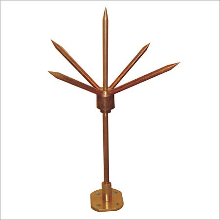
Lightning conductor
The flow of electrons is called the electricity. One way of generating electricity is, as already mentioned, rubbing glass rods and allowing the electric charge to accumulate in the glass rod. This electricity is static. That is it does not flow.
We know that for doing any work, we need a force, which may be a push or a pull. Water in a horizontal tube will not flow, but will be in rest. If we lift one side of the tube, the water will flow. Likewise, in order to drive the electrons to flow, we need a force. The force required is called Electro Motive Force, EMF in short. It is measured in “Volts”. The amount of electrons flow is called the current and is measured in “ampere”. If we push a book along the surface of the table, we may feel an opposing force by the table. This opposing force is called friction. Similarly, when the electrons flow through the wire or conductor, it offers an opposing force against the flow of electrons. This opposing force is called the resistance. It depends on various factors. It is measured in “ohms. “
From the early days, the human race tried to make the EMF. The starting point to the development of electric cells is the experiment by Luige Galvani and his wife Lucia on a dissected frog hung from iron railings with brass hooks. It was observed that, whenever the leg of the frog touched the iron railings, it jumped and this led to the introduction of animal electricity. The first who succeeded in devising a cell was Alessontro Volta of Italy. He devised the first cell in the year 1800. It is called the volta cell. Subsequently Leclanche cell, Daniel cell were developed. The cell we use in wall clocks, torch lights etc. are called dry cells.
Refer the following diagram which represents the volta cell. In the volta cell the EMF was produced by chemical reaction. It has two rods called the electrodes. For simplicity we can call them as terminals. One is made of copper and other of zinc. Both are placed inside a glass vessel. The vessel contains dilute sulphuric acid. When the terminals are connected externally by a small piece of wire, current flows from copper to zinc terminal. The copper terminal is positive and the zinc terminal is negative. In physics, the positive terminal is called the “anode” and the negative terminal is called the “cathode”. Thus in this cell, the energy produced by the chemical reaction among copper, zinc and sulphuric acid, is converted into electrical energy. This was able to produce an EMF of 1.08 volts. The improved forms are Leclanche cell and Daniel cell.
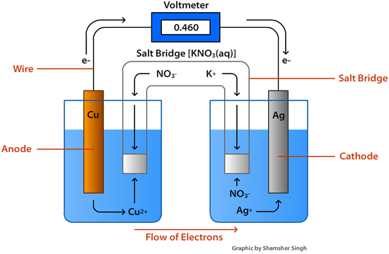
Volta cell
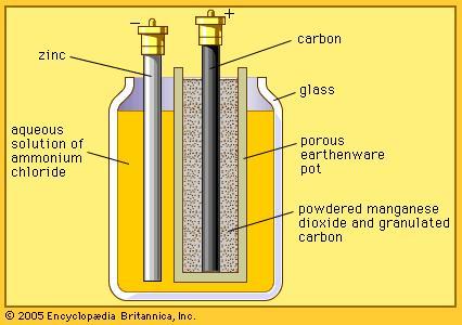
Leclanche Cell
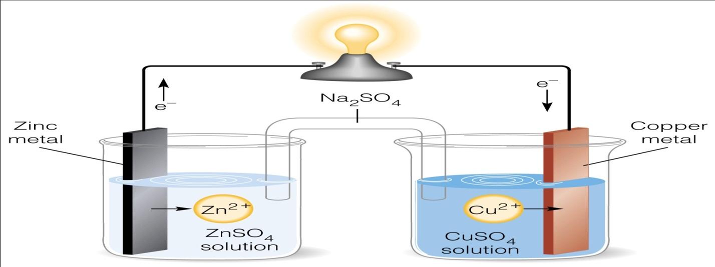
Deniel cell
The cells are classified into primary and secondary cells. The cells which cannot be recharged are called the primary cells and which can be recharged is called the secondary cell. Volta, Leclanche, Daniel and dry cells are primary cells. The cells in mobile phones, car batteries etc are called the secondary cells, since they can be recharged. They are called in different names viz. Lead acid accumulators, lithium cell etc. In this cells also, chemical reaction takes place and chemical energy is converted to electrical energy. While charging, the chemical reaction takes place in the opposite direction and the cell is charged.
The EMF produced by these cells is very low. They are of the order around 1.5 volts only. The EMF is called the Direct current, shortly DC. The drawback of the DC is that they cannot be transmitted to a long distance. The advantage is that they can be stored and we can use whenever we require.
In our school days we have studied about magnets. Practically we might have used magnets at least on few occasions with toys.
A magnet has two ends, called poles. The end which always points the north direction is called the North Pole. The end which always points the south direction is called the South Pole. Around the magnet, there are invisible lines which are called magnetic lines. These lines start from North Pole of the magnet and end at the South Pole. The area in which the magnetic lines are available is called the magnetic field.
The scientists James Clarke Maxwell and Hans Christian Oersted established the relationship between magnetism and electricity. Oersted proved that electricity creates magnetism and magnetism creates electricity. He found that when current is passed through a metal conductor, magnetic lines are produced around the conductor. A devise which generates electricity using magnetism and mechanical energy is called a dynamo or generator.
It was Micheal Faraday, who invented the first dynamo to produce EMF using magnetism. As already stated, there are magnetic lines around a magnet, which is called the magnetic field. Faraday discovered that EMF is produced in a coil which is placed and made to move in the magnetic field. This is because when the coil is moved in the field, the magnetic lines are disturbed or the lines are broken.
Faraday observed that EMF is produced when a metal conductor is moved in a magnetic field or a magnet is moved near the metal conductor. The following experiment conducted by Faraday is very important in the generation of electricity.
Before proceeding to this experiment, let us know what a galvanometer is. A galvanometer is an instrument which looks like the speedometer in the car or a two wheeler. This is used to find the presence of electricity in a circuit. The needle in the galvanometer deflects whenever there is electricity.
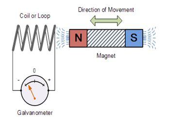
In the above figure there is a coil of wire. The ends are connected to a galvanometer G. A magnet is taken. It is moved from right to left with North Pole directing the coil. When it is moved, the magnetic lines available with the magnet are disturbed and electricity is induced in the coil. The needle of the galvanometer deflects. If we keep the magnet at rest, there is no deflection in the galvanometer. When the magnet is moved away from the coil that is from left to right there is again deflection in the galvanometer but in the opposite direction. From this experiment Faraday formulated the laws of electromagnetic induction. These laws are called Faraday’s laws of electromagnetic induction. If a metal conductor is moved in a magnetic field or a magnet is moved near the metal conductor or the coil, a current is produced in the coil. In short, the motion (coil or the magnet) and magnetism produces electricity. In fact, magnetism and electricity or the two sides of a coin.
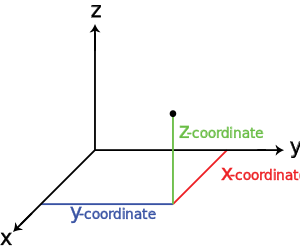
Faraday was the first to construct a dynamo, which produces the EMF, (DC). As per physics, the direction of motion of the metal conductor, magnetic lines and the electricity are in mutually perpendicular directions. We can visualize three mutually perpendicular lines at the top corner or any corner of a room as found in the following figure. We can see three lines meet at that point. These three lines can be taken as the three mutually perpendicular directions. The direction of electricity is decided by the direction of the magnetic lines and also the direction of motion of the conductor. The following rule says about the direction of the electricity if we know the directions of magnetic lines and also the direction of motion of the conductor. This law is known as Flemming’s right hand rule or generator rule or dynamo rule.
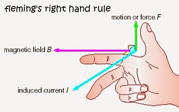
Flemming’s right hand rule or generator rule
Stretch the thumb, fore finger and middle finger of the right hand so that they are perpendicular to each other. If the fore finger indicates the direction of magnetic lines and the thumb shows the direction of the motion of the conductor, then the middle finger shows the direction of the induced current. If the magnetic lines are from right to left on this page, if the conductor moves upwards from this page, then the direction of electricity would be along this page from top to bottom of the page.
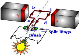
In the above figure ABCD is a coil. It is placed between the two poles of a strong magnet. The coil is devised so that it rotates about an axis.(imagine the rotation of a table fan). The ends of the coil are connected to two split rings S1 and S2. There are two brushes B1 and B2 which are kept pressed to S1 and S2. The rings S1 and S2 will rotate with the coil but B1 and B2 are stationary. Assume that the coil rotates in clockwise direction that is in the direction in which the hands of a clock moves.
The coil rotates in clockwise direction. The magnetic lines are from North to South pole. i.e. from left to right in the diagram. The part CD of the coil is moving from top to bottom. If the diagram is drawn on the table, then CD moves from table towards floor. The direction of magnetic lines is from left to right. By the generator rule, the current in this arm CD is from C to D.
At the same time, the arm AB moves from bottom to top. If the diagram is drawn on the table, then AB moves from table towards roof. By the generator rule, the current in this arm AB is from A to B. Hence the current flows in the direction A-B-C-D. Hence, A is positive and D is negative. That is S1 is positive and also B1 is positive. Similarly, S2 is negative and B2 is negative. If we connect B1 and B2 by a small piece of wire, current will flow from B1 to B2.
After half rotation, the arm CD and S2 will be on the left side. AB and S1 will be on the right side. It may be noted that B1 and B2 would be on the same positions. Now the arm AB is going down and CD is coming up. The magnetic lines are from left to right. As per generator rule, the current in AB is from B to A and for CD it is from D to C . Hence, the current flows in the direction D-C-B-A. S2 is positive and S1 is negative. Now B1 touches S2 and B2 touches S1. Hence, B1 is again positive and B2 is again negative. Hence in the second half rotation also, the current flows from B1 to B2. That is, in this dynamo, the current always flows in the same direction. That is in one direction or unidirectional. This is called the Direct current or DC. If there are large numbers of turns in the coil, the current generated in each turn adds up to give a large current through the coil.
As mentioned earlier, the DC cannot be transmitted to a long distance. This type of generator (dynamo) is used in many electronic appliances. It is used in cars and vehicles.
The production of DC is not sufficient and has the own drawbacks. The current actually we are using in almost all places is called the AC (Alternating Current). This can be transmitted to a long distance, can be increased and decreased whenever we need. Now we will see the working of AC dynamo.
AC Dynamo/Generator
The first AC dynamo was devised by the Yugoslav scientist Nicholas Tesla. The construction is very similar to that of a DC dynamo. Instead of two rings there are two hollow cylinders fixed at the ends of the coil as in the above figure. They are called slip-rings. In this arrangement, during the first half rotation B1 is positive and B2 is negative. In the second half rotation, B1 is negative and B2 is positive. Thus the current alternates and hence it is called Alternating current. Can you understand the working of this dynamo?
In our day to day life we use electric motors in almost all places. For example, fans, mixie, water pumps etc. There are also two types of motors, the DC and AC motors. The construction and working are similar to generators. The difference is that in generator, we make the coil rotate in the magnetic field and gets the electricity. In the motors, we give electricity to a conductor which is placed in a magnetic field, and we get the mechanical energy, the rotation. The following figure will explain the principle of motors. The important thing is that in the case of motors we use Flemming’s left hand rule, which is explained below.
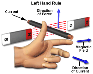
Stretch the thumb, fore finger and middle finger of the left hand so that they are perpendicular to each other. If the fore finger indicates the direction of magnetic lines and the middle finger shows the direction of current in the conductor, then the thumb shows the direction of motion of the conductor.
DC Motor
In the above diagram, the magnetic lines are in the direction of B from north pole to south pole. The direction of electricity I, is along the small red arrow heads shown in the figure. By Flemming’s left hand rule, the direction of rotation is clockwise as seen from the figure. If we change the positions of the magnet or the direction of the electricity, the rotation would be in anti-clockwise direction. You might have observed that a table fan, rotates in clockwise direction, if you are in front of it. On the other hand the ceiling fan rotates in anti-clockwise direction.
The working of AC motor is similar to that of a DC motor, which may be seen from the following diagram.
AC motor
George Simon Ohm established the basic relationship among the voltage, current and the resistance. The voltage is denoted by V, the current by I and the resistance by R. Ohm’s law states that V/I is a constant. In other words V=IR.
The power of electric appliances is denoted by the unit watt. Power is the product of V and I. That is P=VI. You might have observed that in electrical appliances the power is noted as 40 W, 200 W etc. In our domestic circuit, electricity is supplied at 220 volts. All appliances require this voltage. It is important that different appliances require different amount of current (ampere) and hence the consumption of electricity by different appliances is different. For example an electrical bulb is marked as 110 W and the voltage is 220 volts. From Ohm’s law, P=VI. Hence, I=P/V=110/220=0.5 ampere. On the other hand if a mixie is marked as 880 W, it will consume 880/220= 4 ampere.
The product of voltage and current is called the power (watts). 1000 watts is called a Kilo watt. The product of power and time is called kilo watt hour, which we usually called as Unit. We are paying electric charges for this usage. If an electric bulb 100 W is used form 10 hours, the product comes to 1000 which is 1 unit. This consumption would be high for water heaters, air conditioners etc. since they consume high current.
Transformer is an electrical device used for converting low AC voltage into high AC voltage and conversely from high AC voltage to low AC voltage. A transformer which converts low voltage to high voltage is called a stepping-up transformer and one which converts a high voltage to low voltage is called a stepping-down transformer. The transformer works on the principle of electromagnetic induction.
A transformer has two coils called the primary coil and secondary coil. They are wound on a soft iron core. They are insulated from one another. The input AC is given in the primary coil, and the output is taken through the secondary coil. The following figure refers a transformer. Np, Ns, are the number of turns in the primary and secondary coils. Vp, Vs are the voltages in the primary (input voltage) and secondary (output voltage) coils. Ip, Is, are the input and output currents in the primary and secondary coils respectively.
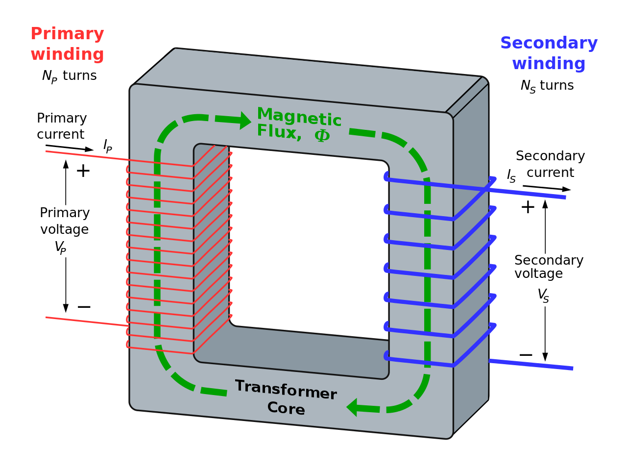
The input AC is applied in the primary coil. As we know, the AC changes its direction continuously and hence the current in the primary is continuously varying. It produces a varying magnetic field in the primary coil. This varying magnetic field is also attached to the secondary coil. Hence an EMF is produced in the secondary coil. (Refer the experiment of Faraday). The input and output of the transformer are connected by the following formula.
ES/Ep=NS/Np=Ip/IS=K
K is called the transformer ratio. If K>1 it is step up transformer, if K<1 it is step down transformer. If K=1, it is called the ideal transformer. If the number of turns in the secondary is greater than the number of turns in the primary, it is called step up transformer. If the number of turns in the secondary is less than the number of turns in the primary it is called step down transformer.
From the above formula we have the following relation between the voltage and current in the primary and secondary coils.
ES/Ep=Ip/IS
The above formula can be written as ESIS=EPIP. From this we can see that when the voltage is increased, the current will be decreased and if the voltage is decreased the current will be increased. This is very important in the transmission of power.
In other words, a step up transformer increases the voltage by decreasing the current. Similarly, a step down transformer decreases the voltage by increasing the current.
In long distance power transmission, there will be power loss due to heating effect. The power loss due to heat is I2RT, where I is the current, R is the resistance and T is the time. This power loss can be reduced by transmitting the power at high voltage with low current, as will be clear from the following examples.
A power of 11000 watt is transmitted at 220 V.
Power P= VI, I=P/V=11000/220=50 A
Power loss =502R=2500R watts.
On the other hand, if this power is transmitted at 22000 V, I=11000/22000=0.05A and hence the power loss =0.25R watts.
Hence it is evident that if power is transmitted at a higher voltage, the loss of energy in the form of heat can be considerably reduced. For transmitting electric power at 11000 W at 220 V the current capacity of line wires has to be 50 A and if transmission is done at 22000 V, it is only 0.5 A. Thus for carrying larger current (50A) thick wires have to be used. This increases the cost of transmission. Also, to support these thick wires, stronger poles have to be erected which further adds on the cost. On the other hand if transmission is done at high voltages, the wires required are of lower current carrying capacity. So, thicker wires can be replaced by thin wires, thus reducing the cost of transmission considerably.
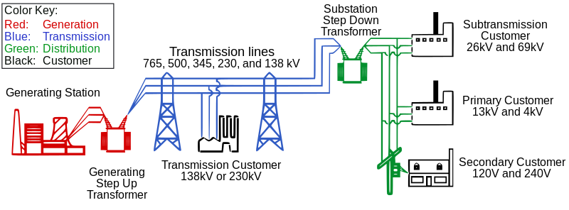
For example 400 MW power produced at 15000 V in the power station is stepped up by a step-up transformer to 230000 V before transmission. The power is then transmitted through the transmission lines which forms a part of the grid. The grid connects different parts of the country. Outside the city, the power is stepped down to 110000 V by a step-down transformer. Again the power is stepped down to 11000 V by a transformer. Before distribution to the use, the power is again stepped down to 230 V or 440 V depending upon the need of the user.
Diagram showing the generation and distribution of AC
The large scale AC generation is done in different ways. In that it is called the armature instead of coils. Turbines are rotated using different forms of energy and turbine is attached to the armature so that electricity is produced. Depending upon the method which is used to rotate the turbine, different names are given. The following are some of the forms of producing electricity commonly used.
Thermal power plant
Coal is burnt in power stations and the heat produced is used to heat water. This water produces steam which runs the turbine.
Hydro power plant
Dams are constructed on the river to obstruct the flow of water and the water is collected in large reservoirs. This water is allowed to flow through large pipes with great force. This force is used to run the turbine.
Wind energy
The wind mill consists of a large structure similar to a fan. It rotates using the speed of the wind. This rotation is used to rotate the armature and thus electricity is produced. A number of wind mills are erected over a large area which is called wind energy farm. The energy output of each windmill in a farm is coupled together to get electricity on a commercial scale.
Solar energy
A large number of solar panels are constructed over a large area. There are two methods used in solar energy. In one method, the sunlight falling on the panels are directly converted into electric energy using the principle photo electric current. In another method, the heat is used to heat up a special kind of oil, which in turn heats up water to produce steam.
Nuclear energy
A process which is called nuclear fission is used in nuclear power stations. It is a process of breaking up of the nucleus of a heavier atom into two parts using neutrons. In this process a large amount is energy is released. This energy is used to heat water to produce steam. The water used in this process is called heavy water.


Comments
Post a Comment
Tell your ideas here